Duffy Information Home Page

Motor Controller and High Voltage Contactors

The information provided is for a 2002 Duffy 18' Classic. Many systems and components are common across models and years.
It is up to you to determine if this information applies to your boat or not.


The motor controller and high voltage contactors are independently serviceable. They are housed together in a box labled "InfaSpeed" located under the operator's seat. The InfaSpeed box provides mount points and a cover for the components as well as modular electrical connections and LED indicators.

InfaSpeed Box

The LEDs show low voltage signals that the motor controller is interpreting from the throttle and key switch inputs. They do not reflect the high voltage outputs from the contactors.


Motor Controller and Contactors

Programmable Motor Controller

The motor controller is an electronic component that serves the following general functions:

Motor Controller

Our motor controller is a Curtis 1204-413

The motor controller also has many programmable settings such as those listed below. This programming was performed by Duffy and the settings are unknown to me.


High Voltage Contactors

Contactor

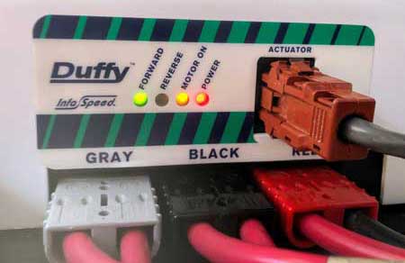
Contactors use a low power input to switch high power circuits. You can hear them mechanically switching (a "clack" sound) as you change throttle modes between off/forward/reverse. All of the high voltage contactors fail safe to "off". An overview diagram showing how the throttle, motor controller, and contactors integrate can be found here.

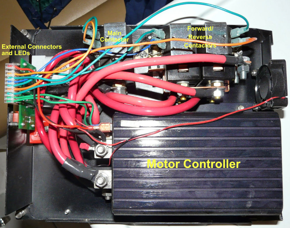
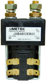
Our contactors are Ametek JAA4602AB00 for the main contactor and Ametek JAM4603AA00 for the forward/reverse contactors. These are rated for 48VDC. You should have functionally equivalent contactors that may have different specifications depending upon your boat's configuration.

The main contactor is a N.O. SPST switch that provides high voltage DC to the motor controller.

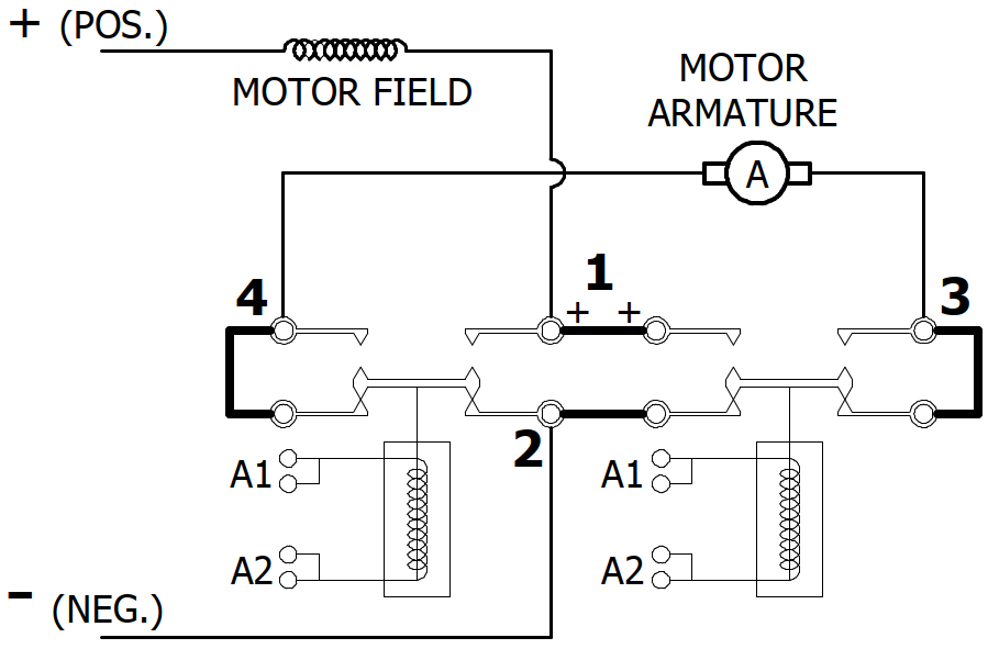
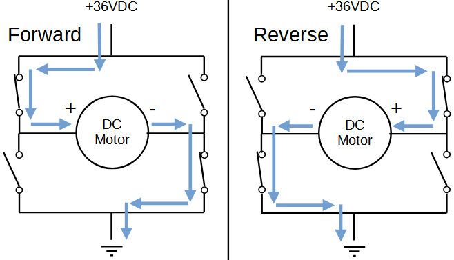
The forward/reverse contactors are N.O. DPDT switches that are paired together to switch polarity to the motor armature to control motor direction. They operate as an H-bridge as follows:

Contactor

The physical implementation is as follows:

Forward/Reverse Contactor Diagram

Duffy Information Home Page