The information provided is for a 2002 Duffy 18' Classic. Many systems and components are common across models and years.
It is up to you to determine if this information applies to your boat or not.
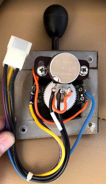
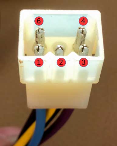
Unscrew and remove the throttle lever and attached wiring until the electrical connector is visible. Tape the incoming wiring harness and connector to the fiberglass housing so that it will be easily accessible later, then disconnect the electrical connector.
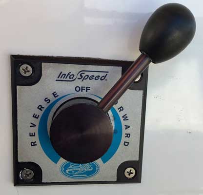
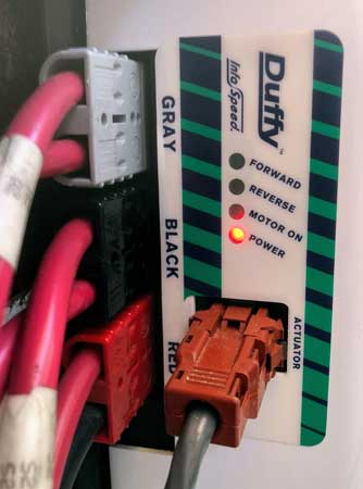
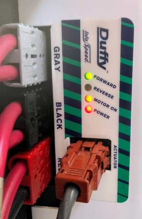
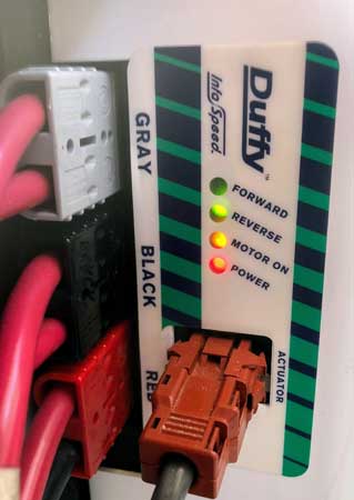
The throttle/actuator provides motor direction and speed inputs per specifications of the motor controller it provides signals to. The motor controller is a commercial product that is housed within a Duffy "InfaSpeed" housing, which also contains mechanical contactors and diagnostic LEDs.
Diagnostic LEDs on the outside of the Duffy InfaSpeed box display signals the motor controller is receiving and whether or not the controller has power. When switching between modes (Forward/Off/Reverse), you should hear mechanical contactors switching from within the InfaSpeed box. These contactors carry high voltage to the motor and fail much more frequently than the electronic motor controller. They may not be providing the required current to your motor even if you hear them opening/closing.
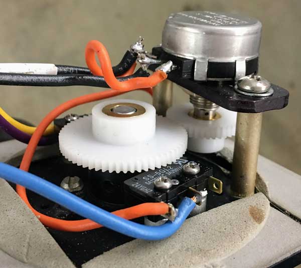
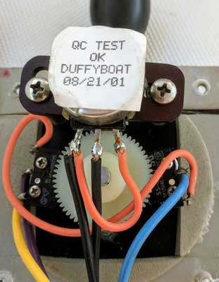
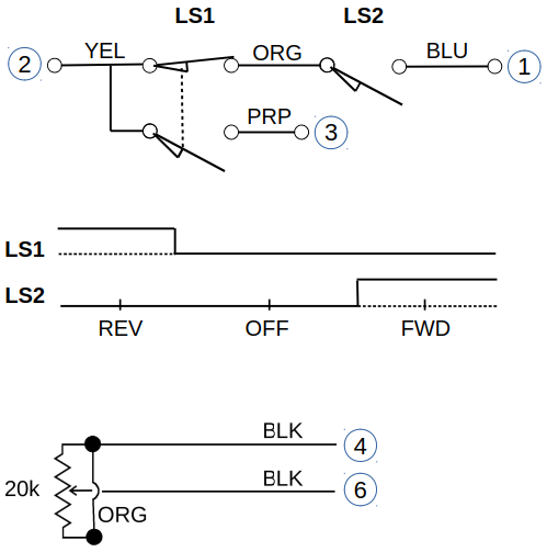
The throttle has two limit switches triggered by a cam on the throttle lever to indicate Forward/Off/Reverse to the motor controller.
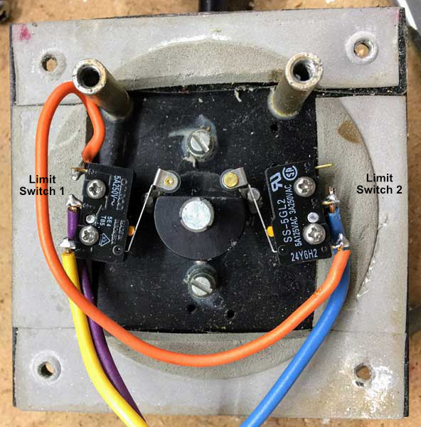
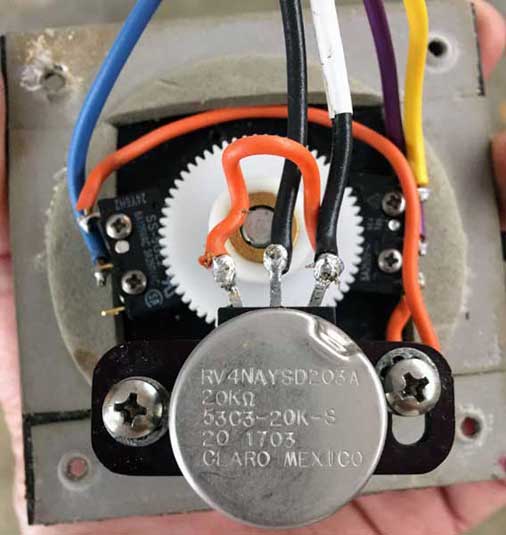
The lever also connects to a 20k ohm* potentiometer which goes from highest resistance when off to near zero resistance at full throttle in either forward or reverse.
Notes:
The throttle and motor controller electrical system is designed to fail-safe. If there is a loss of signal from the throttle, the motor controller will shut off the motor. If the throttle is not in the neutral position when the master switch is turned on, the motor controller will disgregard the signal until the throttle is first returned to neutral.
The mechanical throttle components do not fail-safe. If the gears fail to engage while the motor is on, the throttle can only be shut off by turning off the master key switch. Once this is done, the boat will be dead in the water as the controller requires a neutral throttle position to start, which likely cannot be achieved in this condition.
Adjust the potentiometer until maximum resistance is measured, then mate the potentiometer gear to the throttle lever gear while the throttle is in the "Off" position.
At full throttle in either forward or reverse, you should measure near zero resistance from the potentiometer. Ensure that there is full movement through the 180 degree throttle travel. The throttle lever has physical stops that limit movement when at full forward or full reverse. The potentiometer should not be limiting movement - only the throttle stops.
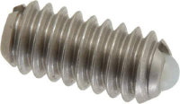
There are two slotted ball-nose spring plungers (top and bottom screws in the picture of the throttle back above) that work as a detent for the "off" throttle position. They also provide physical resistance to hold the throttle at the desired setting. Apply some threadlocker or Teflon tape to fix them in place.
Specs:
Manufacturers: Gibraltar SSWN10-4B-G or Vlier P/N DSSB54N.
Throttle lever travel is 180 degrees. The potentiometer has an effective travel of 270 degrees. To adjust for the different degrees of movement, the throttle lever drives a 60 tooth spur gear mated with a 40 tooth gear that rotates the potentiometer.
The original gears have the larger 60 tooth gear press-fitted directly to the throttle lever. The smaller gear has a set screw and is attached directly to the potentiometer, which has a detent drilled on the shaft. The smaller gear and potentiometer are screwed to an adjustable plate, which is shimmed with washers to enable alignment with its mating gear.
One of our gears was damaged and needed to be replaced. The specs for the original gears are unknown, so we replaced them with a matching set with the same tooth count, 1/4" bore, and approximate outside diameters.
We used machined gears with brass inserts because they were immediately available. The replacement gears each have set screws, which provide a more positive connection than the original press-fit and allow for more precise alignment of the gears. The equivalent molded gears would likely have worked just as well and would have been cheaper.
Replacement Machined Gear Specifications Replacement Molded Gear Specifications
The brass bore of the 60 tooth gear needed to be slightly enlarged to accomodate the throttle lever shaft. The elongated hole on the adjustable plate also needed to be slightly lengthened.